
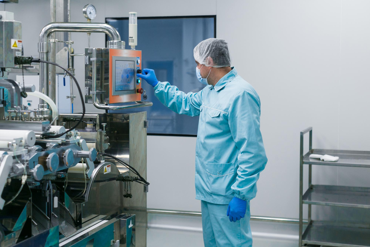
Why vision systems in manufacturing are not all alike
Installing cameras on factory floors requires optical design, lighting engineering, integration with control logic, and validation—not just neural-network training. The core architectural decision — inline versus offline inspection — shapes everything downstream: hardware selection, integration complexity, throughput requirements, and ultimately, what defects you can realistically catch. Getting this decision wrong early means retrofitting later, often at multiples of the original capital cost.
This article covers the practical engineering decisions for manufacturing vision systems: where inline inspection makes sense, when offline is the right choice, how to select camera hardware, what PLC integration actually involves, and what realistic rejection rates look like in production.
How do inline and offline inspection compare?
Inline camera stations sit between fabrication steps, inspecting parts without removing them from the conveyor. Every part is inspected as it moves through the line, at line speed, with no additional handling. The tradeoff: you must work within the constraints of the process — part orientation may be variable, vibration from adjacent machinery affects image quality, and cycle time determines maximum exposure.
Offline inspection routes parts to a dedicated inspection station. This allows controlled lighting, fixed part orientation, and longer exposure times. The tradeoff: it adds a handling step, introduces latency between production and reject detection, and typically inspects a sample rather than 100% of parts.
In our experience, inline inspection is the right choice when:
- Part defects that escape detection have downstream consequences (assembly failures, warranty claims)
- Production rates exceed what sampling can cover reliably
- The defect signature is visually distinct and stable (dimensional variation, surface contamination, colour deviation)
Offline inspection is appropriate when:
- Inspection requires multi-axis imaging (top, bottom, sides) that cannot be achieved inline
- Parts are too complex or variable in orientation to image reliably at speed
- The primary goal is process monitoring rather than 100% sorting (a typical design tradeoff and planning heuristic)
Camera selection: line-scan vs area cameras
Part shape, speed, and surface finish determine whether you need an area sensor that captures entire objects or a line-scan sensor that builds images from motion.
| Parameter | Line-Scan Camera | Area Camera |
|---|---|---|
| Best for | Continuous web, cylindrical parts, fast conveyors | Discrete parts, stationary or slow-moving targets |
| Resolution | Very high in scan direction; unlimited length | Fixed sensor resolution |
| Throughput | High — single line read per encoder tick | Limited by frame rate and exposure |
| Cost | Higher; requires encoder synchronisation | Lower; simpler integration |
| Motion sensitivity | Designed for motion; requires consistent speed | Requires part to be stationary or uses strobed lighting |
| Calibration complexity | Higher — requires flat-field correction | Lower |
Line-scan cameras are the standard choice for web inspection (film, foil, textiles) and for imaging cylindrical parts that rotate past the sensor. For most discrete-part inspection on conveyors, area cameras with strobe lighting are simpler and sufficient.
At 0.5 mm per pixel, that means frame intervals under 0.5 ms, or frame rates above 2000 fps (as a worked example from the stated parameters) — which is impractical with standard industrial cameras.
Why is illumination so often the bottleneck?
Lighting failures derail more vision projects late in deployment than any other single factor, yet illumination often receives the least engineering attention during specification. The model cannot compensate for poor image contrast — if the defect is not visible in the captured image, no amount of training data or model architecture will recover it.
Illumination choices that matter:
- Backlighting: best for silhouette-based dimensional checks; reveals holes, edge profiles
- Coaxial lighting: best for specular surfaces (metal, glass); reveals surface scratches by disrupting uniform reflection
- Ring lighting: general purpose; shadows obscure surface defects on curved parts
- Structured light (line lasers): required for height/3D measurement
Specify illumination before specifying the camera. The camera selection follows from the image you need to capture, not the other way around.
PLC integration and rejection mechanisms
Detection without rejection, rework queues, or line stoppage merely generates dashboards instead of preventing bad parts from shipping. Integration with the PLC (programmable logic controller) is what closes the loop: the vision system signals a reject, the PLC activates a diverter, pusher, or air blast to remove the part from the line.
Typical integration architecture:
- Vision controller outputs a pass/fail signal (digital I/O) or a structured result over Ethernet/IP, PROFINET, or EtherCAT depending on PLC vendor.
- PLC receives the signal, calculates part position using encoder tracking, and activates the rejection mechanism when the part reaches the diverter.
- A rejection confirmation sensor — typically a photoeye after the diverter — confirms the part was actually removed.
The latency budget is tight on high-speed lines. A part travelling at 1 m/s covers 1 mm every millisecond. If the diverter is 500 mm downstream of the camera, the PLC has 500 ms to act — which sounds comfortable, but total latency (image capture + inference + I/O + PLC scan cycle + diverter actuation) must fit within this window. In our experience, total system latency of 50–100 ms is achievable with a well-configured setup using GPU-accelerated inference and dedicated I/O hardware; 200+ ms is more typical for general-purpose deployments and requires increasing the camera-to-diverter distance accordingly.
Realistic rejection rates
Zero-defect claims dominate vision-system sales pitches, yet every deployment eventually confronts the economic and operational trade-offs between false positives and false negatives. The reality is more nuanced and worth being explicit about before signing a capital purchase:
- False reject rate (FRR): Good parts classified as defective. Typically 0.1–2% depending on part variability and inspection difficulty (a rule of thumb from representative industry range). FRR directly costs material and line throughput.
- False accept rate (FAR): Defective parts passing inspection. This is the number that matters to your customer. Target varies by industry: automotive typically requires FAR below 10 ppm; consumer goods may tolerate 100–500 ppm.
- Interaction between FRR and FAR: Tightening the classifier threshold reduces FAR but increases FRR. The operating point is a business decision, not a purely technical one.
Benchmark your system against a manual inspection baseline before deploying. If manual inspection achieves 95% detection at 2% false reject, a vision system should outperform both numbers — otherwise the economics do not justify the capital cost. Across our engagements, well-configured vision systems achieve 99%+ detection with FRR under 0.5% for visually distinct defects on consistent parts. Stretching past that toward “perfect” detection almost always requires either richer training data or a re-think of the illumination geometry, not a better model.
Checklist: vision system readiness before deployment
- Defect library defined with representative samples of every defect type and severity level
- Illumination selected and validated — images show consistent contrast across all defect types
- Camera and lens sized for required resolution at inspection distance
- Trigger mechanism (encoder, photoeye) synchronised and tested at line speed
- PLC integration tested with simulated pass/fail signals before camera integration
- Rejection mechanism physically tested and confirmed at maximum line speed
- False reject and false accept rates measured on held-out test set before go-live
- Operator interface for reviewing rejected parts and false reject recovery defined
Where projects typically fail
Engineering decisions made now—lens selection, trigger timing, calibration routines—directly determine whether your system will handle future part variations and production speed increases.
The vision system is a sub-component of a larger quality control process. Its effectiveness depends on how it is integrated into operator workflows, how rejected parts are reviewed, and how model performance is monitored over time as parts and processes evolve. The deep treatment of where computer vision fits within manufacturing — and where it does not — sits in our broader machine vision vs computer vision discussion. Our Computer Vision R&D practice page is the broader entry point for scoping one of these systems from scratch.
Frequently asked questions
When should we choose inline over offline inspection?
Choose inline when defects escaping into downstream assembly carry real cost, when production rates exceed what statistical sampling can cover reliably, and when the defect signature is visually stable enough to image at line speed. Offline inspection earns its place when parts need multi-axis imaging, when orientation is too variable to handle inline, or when the goal is process monitoring rather than 100% sorting (by definition, inspecting every unit).
Line-scan or area camera — how do we decide?
Line-scan cameras are designed for continuous motion: webs, foils, textiles, and cylindrical parts that rotate past the sensor. Area cameras with strobe lighting are simpler and cheaper for discrete-part inspection on conveyors, and at typical conveyor speeds a short strobe flash (50–200 µs) freezes motion well enough that frame rate stops being the binding constraint.
What latency budget should we plan for between camera and reject?
Plan on total system latency of 50–100 ms for a well-configured setup with GPU-accelerated inference and dedicated I/O, and 200+ ms for more general-purpose deployments — a planning heuristic for scoping hardware. The diverter must sit far enough downstream that the part is still in front of it when the PLC fires — at 1 m/s line speed, every 100 ms of latency costs 100 mm of physical separation (by definition).
What false reject and false accept rates are realistic?
For visually distinct defects on consistent parts, well-configured vision systems achieve 99%+ detection with false reject rates under 0.5% as a rule of thumb for representative performance benchmarks in practice. Automotive customers typically demand false accept below 10 ppm; consumer goods may tolerate 100–500 ppm. Tightening one number worsens the other, so the operating point is a commercial decision, not a purely technical one.
Why is illumination so often the project killer?
Because the model cannot recover information that was never in the image. Ambient light shifts between shifts, reflective surfaces hide scratches under ring lights, curved parts shadow themselves — none of which a classifier can compensate for. We specify illumination geometry and lock it down before camera selection, and we validate contrast across every defect class before any training data is collected.
Why most vision deployments stall at pilot
Successful scale-up from pilot to full production hinges on three factors: reproducible lighting across shifts, documented defect libraries with edge cases, and operator acceptance of occasional false alarms. Revisit it when your workload shifts.